GD&T Symbols Explained for Interview – Easy Ultimate Guide 2026
This article covers the basics of GD&T Symbols (Geometric Dimensioning and Tolerancing) with practical industrial examples and interview-focused explanations. You will learn common GD&T symbols, feature control frame, datums, and tolerances used in quality and manufacturing industries. It is designed for beginners, CNC operators, quality engineers, and mechanical interview preparation.
inforiver
What is GD&T Symbols?
GD&T (Geometric Dimensioning and Tolerancing) is a symbolic language used in engineering drawings to control the shape, position, orientation, and accuracy of a part.
Simple Interview Definition
“It is used to define the allowable variation in a component so parts can fit and function properly during assembly.”
Practical Example:
- A shaft may have the correct diameter but still be slightly bent.
- It helps control such issues so the shaft rotates smoothly inside a bearing.
Why GD&T Symbols is Important in Industry
Benefits
- Improves part accuracy
- Reduces rejection and rework
- Helps proper assembly
- Saves manufacturing cost
Real Industrial Example
In automobile engines:
- If hole positions are slightly shifted,
- Engine parts may not assemble properly,
- Resulting in vibration or leakage.
That is why GD&T is used in:
- Automotive
- Aerospace
- CNC machining
- Quality control
- Tool room
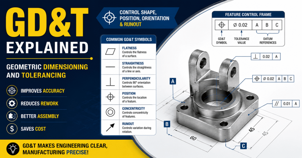
Feature Control Frame in GD&T
A Feature Control Frame (FCF) is a rectangular box containing GD&T information like symbol, tolerance value, and datum reference.
It Contains:
- GD&T symbol
- Tolerance value
- Datum reference
Example
| Symbol | Meaning |
|---|---|
| Position | Hole location control |
| Ø0.02 | Allowed tolerance |
| A B C | Datum references |
Practical Understanding
If a drawing says:
- Position tolerance = 0.02 mm
- It means the hole center can move only within 0.02 mm.
Common GD&T Symbols with Short Definitions
| GD&T | Sign | Simple Definition | Practical Industrial Example |
|---|---|---|---|
| Flatness | ▱ | Controls how flat a surface must be | Engine block mounting surface |
| Straightness | — | Controls how straight a shaft or line should be | Hydraulic rod or guide rail |
| Circularity (Roundness) | ○ | Controls round shape accuracy | Bearing outer diameter |
| Cylindricity | ⌭ | Controls complete cylindrical form | CNC machined shaft |
| Parallelism | ∥ | Controls parallel relationship between surfaces | Sliding fixture plates |
| Perpendicularity | ⊥ | Controls 90° relationship between surfaces | Drill hole in fixture block |
| Angularity | ∠ | Controls angle orientation other than 90° | Chamfer surface |
| Position | ⌖ | Controls exact location of holes/features | Engine mounting holes |
| Concentricity | ◎ | Controls common center alignment | Bearing and shaft assembly |
| Runout | ↗ | Controls wobbling during rotation | Rotating spindle or wheel hub |
Datums in GD&T
What is Datum?
A datum is a reference surface or point used for measurement.
Example:
When inspecting a component:
- Bottom surface = Datum A
- Side surface = Datum B
- Front surface = Datum C
These references help inspect the part accurately.
Practical GD&T Example in CNC Machining
Suppose you manufacture a flange with 4 holes.
Without GD&T Symbols:
- Hole size may be correct,
- But hole positions may shift,
- Bolts will not fit.
Using Position Tolerance:
- Hole location is controlled,
- Assembly becomes smooth.

Why GD&T is Important for Quality Engineers
GD&T Symbols helps quality engineers:
- Inspect parts accurately
- Reduce rejection
- Improve production quality
- Understand engineering drawings easily