GD&T Symbols Explained for Interview – Ultimate Guide 2026
This article covers the basics of GD&T Symbols (Geometric Dimensioning and Tolerancing) with practical industrial examples and interview-focused explanations. You will learn common GD&T symbols, feature control frame, datums, and tolerances used in quality and manufacturing industries. It is designed for beginners, CNC operators, quality engineers, and mechanical interview preparation.
inforiver
Table of Contents
ToggleWhat is GD&T Symbols?
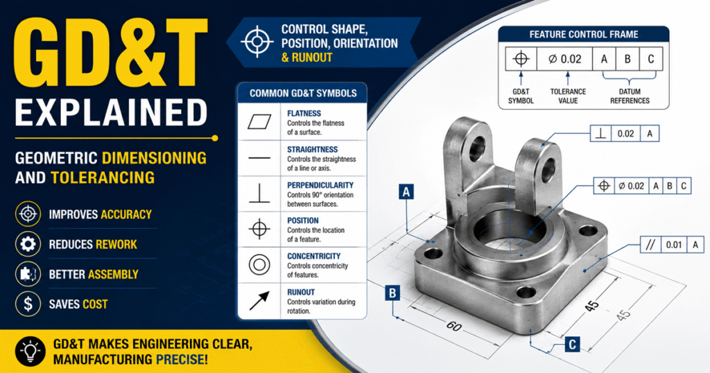
GD&T (Geometric Dimensioning and Tolerancing) is a symbolic language used in engineering drawings to control the shape, position, orientation, and accuracy of a part.
Simple Interview Definition
“It is used to define the allowable variation in a component so parts can fit and function properly during assembly.”
Practical Example:
- A shaft may have the correct diameter but still be slightly bent.
- It helps control such issues so the shaft rotates smoothly inside a bearing.
Why GD&T Symbols is Important in Industry
Benefits
- Improves part accuracy
- Reduces rejection and rework
- Helps proper assembly
- Saves manufacturing cost
Real Industrial Example
In automobile engines:
- If hole positions are slightly shifted,
- Engine parts may not assemble properly,
- Resulting in vibration or leakage.
That is why GD&T is used in:
- Automotive
- Aerospace
- CNC machining
- Quality control
- Tool room
Feature Control Frame in GD&T
A Feature Control Frame (FCF) is a rectangular box containing GD&T information like symbol, tolerance value, and datum reference.
It Contains:
- GD&T symbol
- Tolerance value
- Datum reference
Example
| Symbol | Meaning |
|---|---|
| Position | Hole location control |
| Ø0.02 | Allowed tolerance |
| A B C | Datum references |
Practical Understanding
If a drawing says:
- Position tolerance = 0.02 mm
- It means the hole center can move only within 0.02 mm.
Common GD&T Symbols with Short Definitions
| GD&T | Sign | Simple Definition | Practical Industrial Example |
|---|---|---|---|
| Flatness | ▱ | Controls how flat a surface must be | Engine block mounting surface |
| Straightness | — | Controls how straight a shaft or line should be | Hydraulic rod or guide rail |
| Circularity (Roundness) | ○ | Controls round shape accuracy | Bearing outer diameter |
| Cylindricity | ⌭ | Controls complete cylindrical form | CNC machined shaft |
| Parallelism | ∥ | Controls parallel relationship between surfaces | Sliding fixture plates |
| Perpendicularity | ⊥ | Controls 90° relationship between surfaces | Drill hole in fixture block |
| Angularity | ∠ | Controls angle orientation other than 90° | Chamfer surface |
| Position | ⌖ | Controls exact location of holes/features | Engine mounting holes |
| Concentricity | ◎ | Controls common center alignment | Bearing and shaft assembly |
| Runout | ↗ | Controls wobbling during rotation | Rotating spindle or wheel hub |
Datums in GD&T
What is Datum?
A datum is a reference surface or point used for measurement.
Example:
When inspecting a component:
- Bottom surface = Datum A
- Side surface = Datum B
- Front surface = Datum C
These references help inspect the part accurately.
Practical GD&T Example in CNC Machining
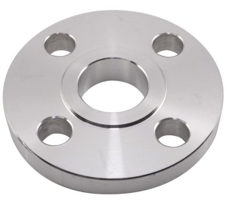
Suppose you manufacture a flange with 4 holes.
Without GD&T Symbols:
- Hole size may be correct,
- But hole positions may shift,
- Bolts will not fit.
Using Position Tolerance:
- Hole location is controlled,
- Assembly becomes smooth.
Why GD&T is Important for Quality Engineers
GD&T Symbols helps quality engineers:
- Inspect parts accurately
- Reduce rejection
- Improve production quality
- Understand engineering drawings easily